Links
Go Up to ER/Studio Business Architect Tools
With a link you create a representation of a relationship between elements. These elements can consist of reference objects, data objects, and elements (including lanes) within a diagram. You can link the Individual Elements (attributes, columns, and data elements) contained in an External Data Objects.
Once you create links you can edit the link and create an Impact Analysis Diagram displaying the link relationships with source and target elements.
- Note: When you create a link, the wizard creates a one-to-many relationship.
Creating a Link
- 1 In the Model View tree, right-click an element (i.e., project, model, pool, lane, or element) and select Links > New
 .
. - OR
- On the main menu select Tools > Create Link and the Create Link Wizard opens for the selected element in the diagram.
- OR
- Right-click an element in the diagram and select Links > New to open the Create Link Wizard.
- OR
- Note: You can also draw a link between two elements by using the Link icon (
 ) on the Reference Objects palette.
 - 2 In the Create Link dialog, you can specify the details for the new link:
- 3 Once you have specified all the details for the new link click OK. You can view this newly created link four different ways:
- Create an Impact Analysis Diagram.
- Right-click either the source or target element in the diagram and select Connections > Show > Links.
- Note: If you have created links between elements that exist in two different processes (for example, in two different diagrams in a workspace or in two different pools), the Show > Links command does not display those links.
- Click the Impact Analysis tab in the either source element, target element or link Property Views.
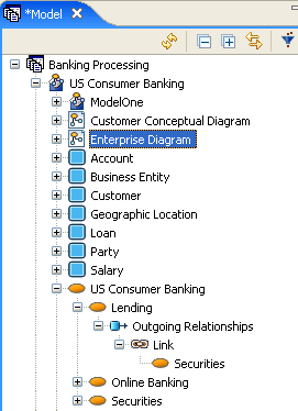
- The created link appears in the Model View tree as a separate folder. In the following example the subject area “Lending” has an outgoing “link” relationship to the subject area “Securities”.
- 4 You can show the link label by right-clicking on the link and selecting Show > Name.
- 5 If you entered a Verb Phrase and/or an Inverse Verb Phrase you can also display them by right-clicking the link and selecting Show.
Connecting Links to Lanes
You can also connect a link to a lane in a pool.
- 1 Click Link (
 ) on the Reference Objects palette.
 - 2 Click on the object you want to connect to the lane and then click in the lane. The following rules apply as to where you click in the lane:
- Draw the link directly to the Lane Header / Name Label to connect to the lane.
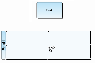
- In order to connect to a lane, the link must be connected closer to the center or inner edge of the lane. Attempting to connect to the upper (or left) portion of the lane will connect to the pool instead.
- The following example shows where you would need to click to connect to a lane. (note where the cursor is in the following illustration).
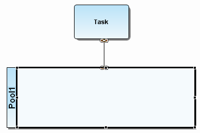
- Once you click in the lane, the link connects to the border of the selected lane.
Editing Links
You can edit links either through the Edit Links dialog or by using the Link’s property view.
- 1 To open the Edit Links dialog, right-click the target element or source element in the model view tree and select Link > Edit. Select the link you want to edit from the pull-right menu displaying the name(s) of the links.
- 2 To open the property view, double-click the link you just created, either in the Model View or in the diagram, and the Property View for that link opens. You can edit the following properties of the link on the General tab.
- 3 The dialog box and the property view contain the same properties which can be edited. However, they are displayed in different formats. The following properties can be edited:
|
Name |
Displays the names of the two linked elements. |
|
Verb Phrase |
Type a verb phrase that describes the relationship from the perspective of the source. For example: EMPLOYEE "owns" RESUME. This label appears on the link where it connects to the source. |
|
Inverse Verb Phrase |
Type a verb phrase that describes the relationship from the perspective of the target. For example: RESUME "is owned by" EMPLOYEE. This label appears on the link where it connects to the target. |
- 4 You can add a description of the link in the Description tab of the Property View and add additional information under the Notes tab.
- 5 You can edit the target element by clicking
on the Source and Targets tab. The Property View for the selected element opens as a tabbed view.
Drawing a Link
Instead of using the Create Link wizard, you can create a link in the Diagram View using the link icon () in the Reference Objects palette or Reference Objects toolbar.
- 1 Click the drop-down arrow on the Reference Objects palette and select Link, or select from the Reference Objects toolbar.
- 2 Click the element that is the origination or source of the link.
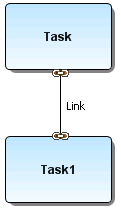
- 3 Click the element that you want the first element linked to (i.e., the target) and a link is created. Link icons are placed on the elements at the beginning and ending of the link.


