Customizing the Layout
Go Up to Customizing the Data Model
Contents
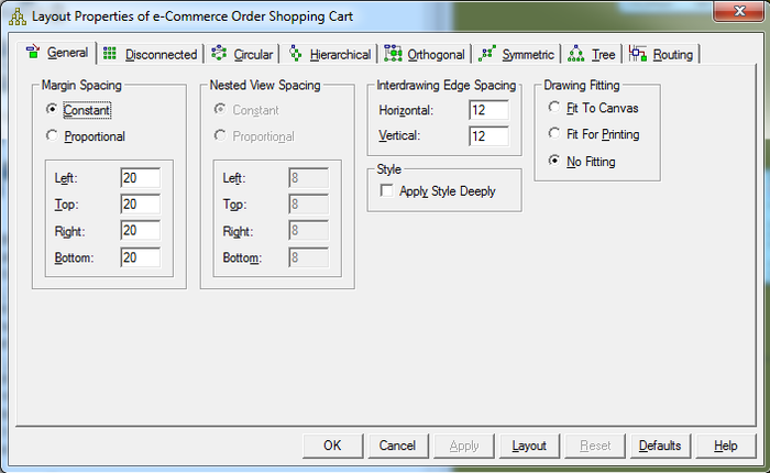
Using the Layout Properties Editor, customize layout properties common to all layouts and customize the appearance of a specific layout method.
![]() Note: Any changes made in the Layout Properties Editor apply only to the model currently selected.
Note: Any changes made in the Layout Properties Editor apply only to the model currently selected.
- In the Data Model Explorer, click the model you want to layout using a customized layout.
- Choose Layout > Layout Properties.
- Click a layout tab.
- Complete the changes as desired.
- Click OK to save the changes and exit the editor.
The following describe options that require additional explanation:
- All tabs
- General tabs
- Disconnected tab
- Circular tab
- Hierarchical tab
- Orthogonal tab
- Symmetric tab
- Tree tab
- Routing tab
All tabs
These buttons are commons to every tab on the editor:
- Ok: Save changes and close the Layout Properties Editor.
- Apply: Applies your changes to all selected diagrams without closing the dialog box.
- Defaults: Resets all values of the selected property sheet to ER/Studio Data Architect default values.
- Layout: Applies your changes to all selected diagrams without closing the dialog box, and immediately displays any changes to the active model in the Data Model Window.
- Reset: Resets all values of the selected property sheet to the values displayed when you opened the Layout Properties Editor.
General tab
- Margin Spacing: Allows you to modify the width of each margin.
- Drawing Fitting: All entities move to fit to canvas or to a print view.
Disconnected tab
- Tiling: Offers three ways of tiling disconnected entities: to grid, to rows, and to columns.
- Tile to Grid: All disconnected entities are spaced evenly apart in a grid.
- Tile to Rows: Maximizes space efficiency by placing entities in rows running left to right, leaving just enough vertical space for the tallest entity in the row.
- Tile to Columns: Maximizes space efficiency by placing entities in columns running top to bottom, leaving just enough horizontal space for the widest entity in the column.
Circular tab
- Spacing:
- Between Nodes: Specifies the distance between entities.
- Between Edges: Specifies the distance between relationship lines.
- Layout Quality: Specifies the speed of the algorithm used to produce the layout.
Hierarchical tab
- Routing: Specifies the nature and look of the relationship lines in the selected data model.
- Incremental Layout: Specifies the retention of familiar component shapes in the Data Model Window. For example, if you produce a data model in one layout style, paste into the window of a data model laid out in a different style, and then join them to make a connected diagram, selecting the Incremental Layout check box preserves the different layout styles as you continue to make modifications to the data modelEdge RoutingV.
- Layout Quality: Specifies the speed of the algorithm used to produce the layout.
- Draft: Provides the lowest quality, but fastest level of layout.
- Proof: Provides the highest quality, slowest level.
- Orientation: Lets you specify one of four ways to orient the data model. Changing data model orientation does not automatically change port specifications, connectors, entity shapes, or constraints, some or all of which can rely on specific sides of entities, making for some complicated side effects of changing the orientation of complex data models. Selecting Rotation Specifications includes port specifications, connectors, entity shapes, or constraints when re-orienting the data model.
- Incremental Layout: Specifies the retention of familiar component shapes in the Data Model Window. For example, if you produce a data model in one layout style, paste into the window of a data model laid out in a different style, and then join them to make a connected diagram, selecting the Incremental Layout check box preserves the different layout styles as you continue to make modifications to the data modelEdge RoutingV.
Orthogonal tab
- Layout Quality: Specifies the speed of the algorithm used to produce the layout. The primary difference between Draft, Default, and Proof quality is the number of times ER/Studio Data Architect runs the algorithm on the diagram. The more often the algorithm runs, the more quality.
- Horizontal Spacing
- Between Nodes: Specifies the horizontal distance between parallel entities.
- Between Edges: Specifies the horizontal distance between parallel relationship lines.
- Vertical Spacing
- Between Nodes: Specifies the vertical distance between parallel entities.
- Between Edges: Specifies the vertical distance between parallel relationship lines.
Symmetric tab
- Layout Quality: Specifies the speed of the algorithm used to produce the layout.
- Draft: Provides the lowest quality, but fastest level of layout.
- Proof: Provides the highest quality, slowest level.
Tree tab
- Undirected Layout: When a diagram is undirected, the source and target entities of any relationship are treated the same. In a directed diagram, the direction of the relationship is significant. Networks are often represented in undirected layouts, while processes are often represented in directed layouts.
Routing tab
- Horizontal Spacing
- Between Nodes: Specifies the horizontal distance between parallel entities.
- Between Edges: Specifies the horizontal distance between parallel relationship lines.
- Vertical Spacing
- Between Nodes: Specifies the vertical distance between parallel entities.
- Between Edges: Specifies the vertical distance between parallel relationship lines.
