UML 2.0 Use Case Diagram Elements
Go Up to UML 2.0 Use Case Diagrams
The following table lists the elements of UML 2.0 Use Case diagrams that are available using the Tool Palette:
UML 2.0 Use Case diagram elements
| Icon | Element | Name | Type | Comment |
|---|---|---|---|---|
|
Actor |
Node |
|||
|
Use Case |
Node |
|||
|
Subject |
node |
|||
|
Association |
Link |
|||
|
Extends |
Link |
|||
|
Includes |
Link |
|||
|
Generalization |
Link |
|||
|
Node by |
Node |
Opens Pattern Wizard | ||
|
Link by |
Link |
Opens Pattern Wizard | ||
|
Note |
Annotation |
|||
|
Note |
Annotation |
You see the note connected by the note link with another modeling element. | ||
|
Image |
Illustration |
The Tool Palette command puts on a diagram only the empty frame of the image placeholder. To render an image in this frame:
Here you see the Embarcadero image, rendered in the frame of the image placeholder. | ||
|
Image |
Illustration |
You see the Embarcadero image connected by the image link with another modeling element. | ||
|
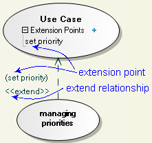
Extension |
Node |
Create an extension point in a use case to specify a point in the behavior of a use case, where this behavior can be extended by the behavior of some other use case. That is, an extension point refers to a location within a use case where you can insert action sequences from other use cases.
| ||
|
Activity |
Node |
This element is available on the context menu of a use case. | ||
|
Interaction |
Node |
This element is available on the context menu of a use case. |


