UML 2.0 Class Diagram Definition
Go Up to UML 2.0 Class Diagrams
UML 2.0 Class diagrams provides similar capabilities as the UML 1.5 class diagrams.
Contents
New UML 2.0 Features
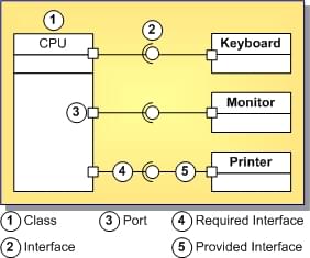
Class diagrams in UML 2.0 offer new diagram elements such as provided and required interfaces, ports, and instance specifications.
Provided and Required Interfaces
Class diagrams in UML 2.0 support all relationships among diagram elements -- generalization and implementation, dependency, and association (association, aggregation, and composition) -- that are supported in UML 1.5 class diagrams. (See Relationships Among Elements of Class Diagrams.)
Notice that in UML 2.0, as UML 1.5, an interface can have an implementation relationship with a class. This implementation relationship is specified by the same implementation link as in UML 1.5 class diagrams.
However, UML 2.0 class diagrams, in addition to an implementation relationship, introduce the provided and required interfaces. To mark provided and required interfaces, UML 2.0 class diagrams use the provided interface ![]() ("lollipop" notation) and required interface
("lollipop" notation) and required interface ![]() ("soket" notation) links (see UML 2.0 Class Diagram Elements).
("soket" notation) links (see UML 2.0 Class Diagram Elements).
On UML 2.0 class diagrams, interfaces can be represented both in the UML 1.5 style, by rectangles  , and in the new UML 2.0 style, by circles
  . Circles hide internal members of interfaces. For the sake of clarity of your diagrams, you can switch between these representations using the View as Class property in the Object Inspector.
- Tip: Applying a provided interface link between a class and an interface creates a regular generalization/implementation link. To create a provided interface, apply the provided interface link to a port on the client class.
Ports
A port is a property of a classifier that specifies a distinct interaction point between that classifier and its environment or between the classifier and its internal parts.
The interfaces associated with a port specify the nature of the interactions that may occur over a port. The required interfaces of a port characterize the requests that may be made from the classifier to its environment through this port. The provided interfaces of a port characterize requests to the classifier that its environment may make through this port. A port has the ability to specify that any requests arriving at this port are handled by the behavior of the instance of the owning classifier, rather than being forwarded to any contained instances, if any.
Instance Specifications
An instance specification specifies the existence of an entity that represents an instance of a model element in a modeled system and completely or partially describes the entity. An instance specification can instantiate one or more classifiers. Instance Specification is a concrete class (a class from which you can create an instance because it has a full implementation). The entity description may include:
- Classification of the entity by one or more classifiers of which the entity is an instance.
- The kind of instance, based on its classifier or classifiers.
- For example, an instance specification whose classifier is a class describes an object of that class.
- Specification of values of structural features of the entity.
- Specification of how to compute, derive, or construct the instance.
An instance specification owns slots. A slot specifies that an entity modeled by an instance specification has a value or values for a specific structural feature of a classifier of the instance specification.
Class Diagram Types
There are two types of class diagrams used in the Modeling:
- Package diagrams. Package diagrams are stored as XML files with the
.txvpckfile extension in theModelSupport_%PROJECTNAME%folder of the project group. - Logical class diagrams. These diagrams are stored as XML files with the
.txvclsfile extension in theModelSupport_%PROJECTNAME%folder of the project group.
The Modeling automatically creates a default package diagram for the project and for each subdirectory under the project directory. The default package diagram is named default. Other automatically generated default package diagrams are named after the respective packages.
You create logical class diagrams manually using the Add > Class Diagram or Add > Other Diagram commands on the context menus in the Diagram View or Model View.
Sample Diagram
The figure below shows a class diagram with some of the new elements.
