Processes - Business Process Modeling
Go Up to Using ER/Studio Business Architect
Business Processes
When working in ER/Studio Business Architect you have two different types of models, Conceptual and Business Process. When working with Business Process models, you work with Processes. This section discusses how processes are used when working with Business Process models.
A Process is a collection of flow objects connected by flows that is executed in a sequence (usually depicted on a diagram). In ER/Studio BA, all processes are contained by a pool. A pool contains only one process, but you can have multiple pools in a diagram which can then collaborate via messages.
You can set a preference to display elements in a diagram or pool under the Process node () in the Model View. If this option is not selected, all elements are displayed under the Pool node.
In the Business Process Modeling Notation Specification, all Business Process Diagrams must contain at least one pool. In ER/Studio BA, when you Diagram, a pool and lane with an invisible boundary are created as well. In ER/Studio BA, when you place an object in the diagram, that object is automatically placed in the pool.
Initially when you create the diagram, the pool and lane are given a default name. You can rename both the created pool and its associated lane.
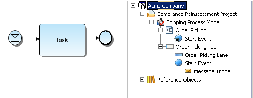
In the following example, the diagram contains a pool with an invisible boundary (named Order Picking Pool) and is indicated by the icon in the Model View tree. The lane, named Order Picking Lane, is “owned” by the pool. The event is owned by the process, but since the process is hidden, it appears under the pool.
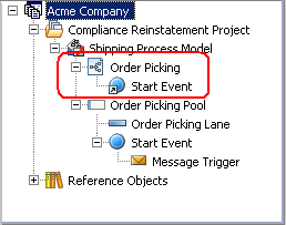
- When you place an element, for example a Start Event, that start event is shown as a presentation element under the Diagram node (this is indicated by an arrow symbol placed on the icon ).
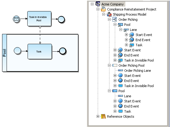
In the following example, the model contains one visible pool/lane and one invisible pool/lane. The Model View tree displays the elements under the pool. However, in the diagram node, the presentation elements are displayed under the lane node to show their location within the lanes depicted on the diagram.
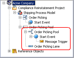
- If you select the preference to show process in the application the elements in a pool are displayed under the Process node.
Conceptual Diagrams
Conceptual modeling is used by enterprise architects, business users, and data architects to model information about the business as it relates to mostly to data. However it could include other things like data flow, process, or information assets. The conceptual model is used to drill down into more detail which would be Process models and Logical/Physical data models. It simplifies the organization of hundreds if not thousands of physical objects. It is powerful enough to link to further technical (or physical) detail, but simple enough to communicate to non-technical users.


