Creating and Editing Relationships
Go Up to Developing the Logical Model
Contents
- On the Data Model Explorer, click the Data Model tab.
- To create a new relationship
- Choose Insert > Relationship and then click the type of relationship you want to insert.
- On the Data Model Window, click the parent object and then click the child object.
- The Duplicate Attribute Editor displays If both the parent and child objects have the same column or attribute names. Here you can resolve these conflicts by assigning rolenames to foreign keys.
- The Recursive Relationship editor displays when you create a recursive relationship, which is a non-identifying relationship where the parent and child object are the same. Using this editor you can assign rolenames to any duplicate keys to differentiate the native and foreign key. For more information, see Creating and Editing Recursive Relationships.
- The Duplicate Relationship editor displays when you draw a relationship that will result in multiple identifying and/or non-identifying relationships between two entities. Using this editor you can assign rolenames to any overlapping foreign keys; otherwise, ER/Studio Data Architect unifies any overlapping Foreign Keys.
- The Edit Rolenames dialog displays if overlapping foreign keys are detected when you are drawing a relationship. On the Edit RoleNames dialog you can specify rolenames for foreign keys that are inherited more than once. When a primary key is propagated to a child table, the name of the attribute is also propagated to the child table. A rolename lets you rename the attribute of the foreign key to avoid confusion and resolve the relationship conflict.
- Repeat steps 2 and 3 until you have created all necessary relationships.
- To revert to the Selection tool, right-click anywhere on the Data Model Window.
- To edit an existing relationship
- On the Data Model Window, double-click the relationship
- Complete the Relationship Editor and then click OK to exit the editor.
All tabs
- Parent Key: Lets you select and propagate an Alternate Key (logical model) or a Unique Index (physical model) to a child entity or table. Use this option if you do not want to propagate the primary key. If there are no alternate keys or unique indexes in the parent table the primary key will be used.
- Logical Only: Logical model only. If selected, the relationship will not be implemented when generating a physical model, and will be ignored when comparing the logical model with a physical model.
- Physical Only: Physical model only. If selected, the relationship will be ignored when comparing the physical model with a logical model.
- NoValidate: This option is available for the Oracle 9i, 10g, 11g and 12c platforms. Specify NoValidate if you do not want the constraint to be applied to the data in the table.
If generation of the FK or PK constraint is enabled, NOVALIDATE will be generated if the option is set for the constraint. For example, if the PK is not disabled, but NoValidate is set, the DDL would be
CREATE TABLE Entity1
(
PKCOL CHAR(10) NOT NULL,
CONSTRAINT PK1 PRIMARY KEY (PKCOL) NOVALIDATE
);
The same syntax will be used for FKs when created inside the CREATE TABLE or by ALTER TABLE.
ALTER TABLE ENTITY2 ADD CONSTRAINT BLIVOT
FOREIGN KEY (PK1)
REFERENCES ENTITY1(PK1) NOVALIDATE
If Disable is set but NoValidate is not set, the DDL for an FK created by ALTER TABLE would be the following, since NOVALIDATE is the default option. The same syntax is used for PKs.
ALTER TABLE ENTITY2 ADD CONSTRAINT BLIVOT
FOREIGN KEY (PK1)
REFERENCES ENTITY1(PK1) DISABLE VALIDATE
- Do Not Generate: Physical model only. If selected, the foreign key (FK) columns (if any) will be ignored when generating DDL, as in the Compare and Merge Utility. The FK constraint is not generated but the FK column is generated as a native column. To prevent the FK from being generated, edit the FK column in the Table Editor and select the Hide Key Attribute option. Use this option when relational integrity is enforced in the application rather than by an explicit foreign key in the RDBMS.
- Not For Replication: If selected, updates to the parent will not be replicated to the child entity. This prevents any foreign key constraints from being applied when updating the child entity.
- NO CHECK: This option is used when creating FK constraints in Teradata V2R6 and later databases to disable constraint data checking when performing SQL operations on the data in the table the FK is created on.
- NOCHECK: This option is used when creating FK constraints in SQL Server 2005 or and later to disable checking of existing data against the contraint during the add operation. In addition, the FK constraint is disabled and future inserts or updates to the column are not validated against it.
- Deferrable: Physical model only. If selected, the REFERENCES.... DEFERRABLE syntax will appear in the FK DDL for inline (in the create table) or ALTER (out of the create table). The DEFERRABLE statement becomes part of the constraint state logic after the REFERENCES clause.
In general, the DEFERRABLE parameter indicates whether constraint checking in subsequent transactions can be deferred until the end of the transaction using the SET CONSTRAINT(S) statement. If omitted, the default is NOT DEFERRABLE. If a constraint is deferrable in the model but not deferrable in the database it will need to be dropped and recreated with the deferrable constraints. See Oracle syntax documentation for a description of deferrable constraints. - Initially Deferred: Physical model only. If Deferrable is selected, this option becomes available. When selected, the REFERENCES... DEFERRABLE INITIALLY DEFERRED syntax appears in the DDL for the child table in the relationship. Initially deferred indicates that constraint checking is postponed until the end of the transaction.
- Disable: This option is available for the Oracle Platform only. If selected, disables the foreign key of a child entity. The following is an example of the DDL generated for the child entity when the FK is disabled:
CREATE TABLE Entity2(
PK2 CHAR(10) NOT NULL,
a2 CHAR(10),
b2 CHAR(10),
PK1 CHAR(10) NOT NULL,
CONSTRAINT PK2 PRIMARY KEY (PK2),
CONSTRAINT RefEntity11 FOREIGN KEY (PK1)
REFERENCES Entity1(PK1) DISABLE
Properties tab
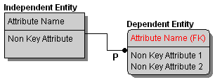
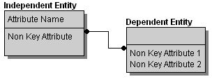
- Relationship Type > Identifying Relationships Identifying relationships are always mandatory. A foreign key value must exist in the child entity and the foreign key value must be found in the primary key of the parent. Identifying relationships propagate primary keys as primary keys to child entities, which can result in compound keys.
The use of compound keys is often valid and appropriate; however, they limit the flexibility of your data model. When you use a compound key, the data contained in the child entity can only be identified in the context of its parent. If you ever need to use the data independently, then you will have a problem
The cardinality of a mandatory relationship must be in the form of one-to-something.
When generating a physical model, foreign key columns propagated by a mandatory relationship default to NOT NULL.
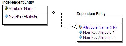
- Relationship Type > Non-Identifying, Optional Relationships: Non-identifying relationships propagate the parent's primary key to the non-key attributes of the child. Since the relationship is optional the foreign key value is not always required in the child entity; however, if a value does exist, then the foreign key value must be found in the primary key of the parent.
The cardinality of an optional relationship takes the form of zero or one to something.
When generating a physical model, foreign key columns propagated by an optional relationship default to NULL.
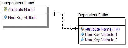
- Relationship Type > Non-Identifying, Mandatory Relationships: Non-identifying relationships propagate the parent's primary key to the non-key attributes of the child. A foreign key value must exist in the child entity and the foreign key value must be found in the primary key of the parent.
The cardinality of a mandatory relationship must be in the form of one to something.
When generating a physical model, foreign key columns propagated by a mandatory relationship default to NOT NULL.
- Relationship Type > Non-Specific Relationships: Non-specific relationships denote many-to-many relationships. Because many-to-many relationships cannot be resolved, non-specific relationships do not propagate any foreign keys. Many-to-many relationships are undesirable and should be removed as you normalize your data model.
The following illustrates a non-specific relationship where the parent and the child are both optional. In the Relationship Editor you can specify whether the parent and the child are optional or mandatory.
- Cardinality: Cardinality displays the ratio of related parent and child instances. The cardinality ratio for the parent depends on whether the relationship is mandatory or optional. Although cardinality is a powerful concept for expressing business rules, you should know that no database can directly enforce cardinality. Enforcing cardinality constraints can be accomplished through procedural database logic or somewhere other than in the database.
The iconic cardinality representations for IE (Crows Feet) notation are illustrated below:
|
Non-Identifying Relationship | ||
|---|---|---|
|
Identifying Relationship |
Optional |
Mandatory |
![]() Note: If you are using a database that supports containment relationships, for example MongoDB, you may also see the following type of relationship.
Note: If you are using a database that supports containment relationships, for example MongoDB, you may also see the following type of relationship.
In a containment relationship, the * or 1 indicates either an array or a single nested object.
Phrases tab
- Verb Phrase: Describes the relationship of the Parent table to the Child table.
- Inverse Verb Phrase: Describes the relationship of the Child table to the Parent table.
Name tab
- Business Name: Identifies the relationship for business documentation purposes.
- Constraint Name: Names the referential constraint the relationship enforces between parent and child tables, if any. ER/Studio Data Architect uses this name as the foreign key constraint name when generating DDL.
Trigger tab
Select a trigger to maintain referential integrity for INSERT, UPDATE, and DELETE operations on child and parent objects. Select one of the following triggers for each operation.
- Restrict: Verifies the existence of foreign key values in the object's primary key and prevents the insertion, updating, or deleting of data if the values cannot be validated.
- Cascade: Propagates any modification of a primary key value to the corresponding foreign key values in the child table.
- Set Null: Verifies the existence of the foreign key values in the parent table's primary key. If the values cannot be validated, the trigger sets the foreign key values to null in the child table and lets the data modification operation proceed.
For more information, see Creating and Editing Database Schemas.
Definition tab
Enter or edit a definition for the relationship. If the target database supports it, ER/Studio Data Architect adds this definition as a comment when generating SQL code.
Compare Options tab
Allows you to choose which properties of the attribute will be ignored when using the Compare and Merge, thus allowing you to have intentional discrepancies.
Note tab
The notes added here are included as part of the HTML report when you generate a report for the model. You can format the notes using standard HTML tags.
Rolename tab
You can change the rolename of foreign keys to differentiate between child and parent attributes in the event that overlapping foreign keys exist. To change a rolename, double-click any of the rows to invoke the Foreign Key dialog. You can also change logical and default column rolenames through the Columns tab of the Table Editor or by right-clicking the relationship and selecting Edit RoleName.
Attachment Bindings tab
Bind an external piece of information, or attachment to the relationship. You can also remove an attachment from an object, override an attachment binding's default value, or change the position of a bound attachment. To override the value of the attachment you have moved to the Selected Attachments grid, double-click the Value field of the target attachment. ER/Studio Data Architect opens the Value Override Editor or a list depending on the attachment datatype. Attachments are created in the Attachments folder of the Data Dictionary and must be applied to the relationship before they will display on this tab. For more information, see Attaching External Documents to the Data Model.
Notes
- You can view the incoming and outgoing relationships of a table by expanding the relevant table node and then expanding I ncoming Relationships or Outgoing Relationships. Expand the relationship node to see the name of the related table.
- You can change the relationship type, specify cardinality, create verb phrases to describe the relationship, create a logical business and constraint name, and define triggers by double-clicking the relationship, and then making your changes in the Relationship Editor.
- You can delete a relationship by right-clicking it in the Data Model Window and then selecting Delete Relationship.
- You can edit a relationship by right-clicking the relationship in the Data Model Window and then selecting Edit Relationship for a logical model or Edit Foreign Key for a physical model.
- Changing relationship types causes ER/Studio Data Architect to re-propagate foreign keys using the following rules:
- When changing from identifying to non-identifying, foreign keys change from primary keys to non-key columns in the child object.
- When changing from identifying to non-specific, or from non-identifying to non-specific, the foreign keys are removed from the child object.
- When changing from non-identifying to identifying, the foreign keys change from non-key to primary key columns or attributes in the child object.
- When changing from non-specific to identifying, the child object inherits the parent object's primary keys as primary key columns or attributes.
- When changing from non-specific to non-identifying, the child object inherits the parent table's primary keys as non-key columns or attributes.
- You can configure how ER/Studio Data Architect displays relationships for the selected model by choosing View > Diagram and Object Display Options Editor > Relationship and then making your changes.
- You cannot edit a View Relationship (see Creating View Relationships).
See Also
Moving Relationship Docking Points
Setting the Relationship Notation
Manipulating Relationship Lines


