Working with Universal Mappings
Go Up to Developing the Logical Model
Contents
Universal Mappings have been implemented to support enterprise-level modeling in large organizations with many systems and overlapping data and processes. They allow you to map objects between models in the same dm1 file, between models in separate dm1 files, and between an ER/Studio Data Architect diagram and a ER/Studio Business Architect workspace in the Repository. These mappings are retained and can be used when comparing and merging. They are automatically applied in the Compare and Merge Utility if they exist.
What is a mapping?
A mapping is a link between two objects. There are two types of mappings that serve different purposes.
- Mappings within a design layer: This horizontal type of mapping shows reuse within a design layer, such as logical to logical, physical to physical and conceptual to conceptual. The scope of this mapping is limited to mapping objects of the same type, such as entity to entity, table to table, and column to column.
- Mappings across different design layers: This vertical type of mapping shows traceability or where used, upstream and downstream across different design layers, such as: conceptual to logical; logical to physical; and logical and physical.
Why are cross-repository mappings important?
- Impact Analysis: Understanding where common objects are located. Traceability between conceptual and logical models.
- Scalability: A mapping system across dm1s and workspaces reduces the need for large models that have everything in them. You can now perform Where Used (ER/Studio Data Architect) or Impact Analysis (ER/Studio BA) that can include information on multiple dm1 or workspace files. Organizing objects into different dm1s or workspaces and then mapping related objects scales much better.
- Performance: Smaller dm1 or workspaces improves performance and manageability.
- Enterprise Modeling: Facilitates an enterprise view of your data. Typically this starts with identifying subject areas, then conceptual entities and then logical/physical models from the conceptual. Once the hierarchy is in place, you can see upstream from logical/physical objects and downstream from conceptual and process models.
The following topics help you understand how Universal Mappings are implemented in ER/Studio:
- Creating Universal Mappings through the Compare/Merge Utility
- Creating a Universal Mapping using the Universal Mapping Editor
- Editing Universal Mappings
- Viewing Universal Mappings
Creating Universal Mappings through the Compare/Merge Utility
The following illustrates the process of creating and using a Universal Mapping:
- User-Defined Mappings can be used in a similar way when comparing between two models in the same dm1 file. Existing user-defined mappings will now be considered when matching in the compare/merge, and you will have the option to save matches as User-Defined Mappings for inter-diagram comparisons.
- The precedence for matches in the Compare/Merge Utility is as follows, from high to low precedence: force matches, universal mappings, name matches, attribute sequence number and datatype matches. In other words, if the datatype matches between two attributes but the universal mapping matches one of those attributes to a different attribute, then the second match will be automatically applied. You can use Force Match in the Compare and Merge Utility to implement a different match.
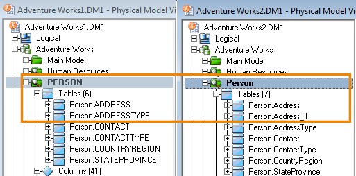
In the following image, we see two dm1 files that differ slightly.
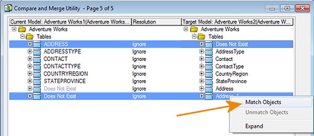
The Compare and Merge Utility automatically matches Person.ADDRESS to Person.Address, but if we want to match Person.ADDRESS to Person.Address1, then we can unmatch these attributes and create a different match.
To illustrate the power of Universal Mapping, we can match two objects and then have the matches saved.
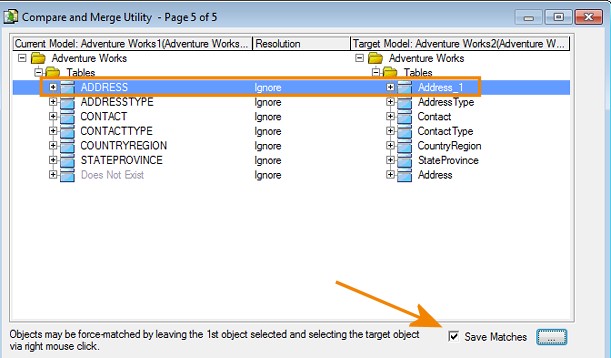
As indicated in the Compare and Merge Utility, 'Objects may be force-matched by leaving the 1st object select and selecting the target object via right mouse click.'
Now that the match is made, we can choose to save the match to use the next time we compare these two models. The matches are saved in both the current and target models.
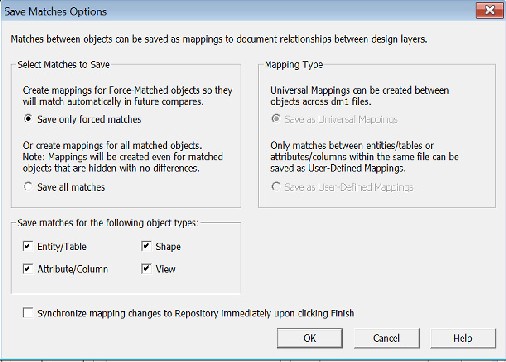
You can click the ellipses to see the Save Matches Options and make your choices.
A checkbox for each object type supported, Entity/Table, Attribute/Column, View, and Shapes is listed and all are selected by default. Only objects of the types selected are eligible to have matches saved as mappings.
When comparing models in the same diagram, you can choose between Save as User-Defined Mappings or Save as Universal Mappings.
When comparing models in different diagrams, Save as Universal Mappings is selected. This is the only option available.
If you are comparing two diagrams in the Repository, the option to Synchronize mapping changes to Repository immediately upon clicking Finish becomes available.
Click OK on the Save Matches Options and then click Finish to complete the compare/merge.
When you run the Compare and Merge Utility again, you will see that the matches you forced and saved are used by default.
Creating a Universal Mapping using the Universal Mapping Editor
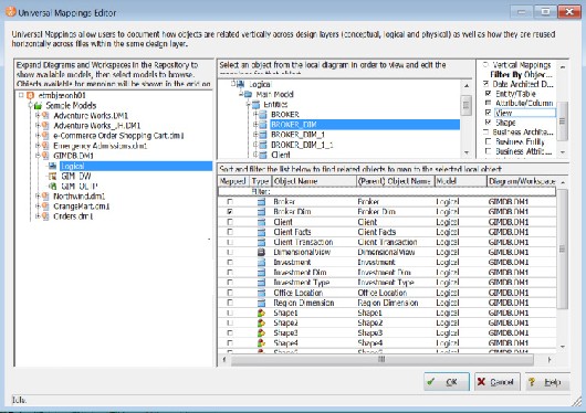
The Universal Mappings Editor provides the following functionality:
- Local Objects You can edit the Universal Mappings of a source object without exiting the Universal Mapping Editor.
- Browse/Filter/Search: You can view objects in other diagrams and workspaces that can be mapped to the currently selected object. Because the number of objects can potentially be very large, you can narrow down the list by using the filters available and sorting the related objects.
- Existing Mappings: You can see which objects are already mapped, as well as the description and any other data associated with the mapping.
- In the diagram window, right-click the object you want to map or change the mapping for and select Universal Mappings.
- In the Universal Mapping Editor, in the center of the window, as indicated onscreen, Select an object from the local diagram in order to view and edit the mappings for that object.
- On the far left of the screen select a model in the tree. Once you have selected the model, the data for it is retrieved from the Repository.
- The list of mappable objects that displays on the bottom right of the editor is generated from your selection in the Repository tree. If you select a diagram node, then all objects in its models will be included in the mappable object list. If you select a Project, then all objects in diagrams in that project will be included.
- On the far right of the editor, select the filters to use in order to see the objects of those type you can map to.
- You can map ER/Studio Data Architect entities/tables, attributes/columns, views, shapes and ER/Studio Business Architect entities, attributes, and subject areas to each other, including mapping ER/Studio Data Architect objects to ER/Studio BA objects.
- At the bottom of the editor, click a column name to reorder the list of related objects to find the object to map to the local object.
- Deselect or select the target object's Mapped checkbox to remove or add a mapping.
- Click OK to complete the change.
- Save your diagram and in the case of Repository diagrams, check in the affected object to save the mapping change to the Repository.
Editing Universal Mappings
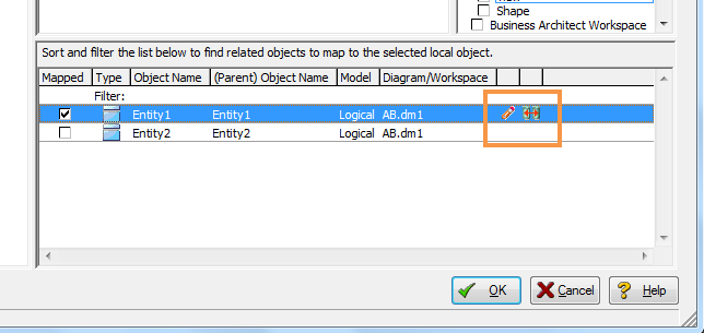
If you want to add additional information about this universal mapping, such as a table comment or a file, you can add it using the tab available on the Edit Universal Mappings dialog. When the Mapped checkbox is selected for a mapping, an icon ![]() appears on the same line, allowing you to open the Edit Universal Mappings dialog.
appears on the same line, allowing you to open the Edit Universal Mappings dialog.
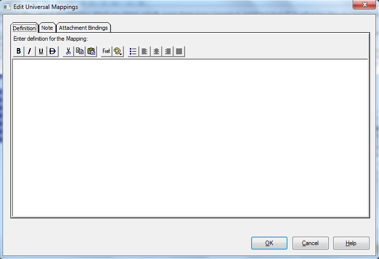
Clicking the icon opens the Edit Universal Mappings dialog. This dialog includes the Definition tab, Note tab, and Attachment Bindings tab, as shown in the following image.
The tabs allow you to add or edit a mapping definition, note using a free text field, or attachment bindings. If one of these items is added to a mapping, a meta data icon ![]() appears next to the edit icon.
appears next to the edit icon.
The following helps you complete the options of the Edit Universal Mappings dialog:
Definition tab
Enter or edit a definition for the universal mapping. If the target database supports it, ER/Studio Data Architect adds this definition as a table comment when generating SQL code.
Note tab
This is a free-form text area to add any additional information concerning this mapping.
Attachment Bindings tab
Bind an external piece of information, or attachment to the universal mapping. You can also remove an attachment from an object, override an attachment binding's default value, or change the position of a bound attachment. To override the value of the attachment you have moved to the Selected Attachments grid, double-click the Value field of the target attachment. ER/Studio Data Architect opens the Value Override Editor or a list depending on the attachment datatype. Attachments are created in the Attachments folder of the Data Dictionary. For more information, see Attaching External Documents to the Data Model.
Viewing Universal Mappings
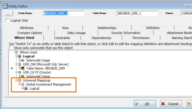
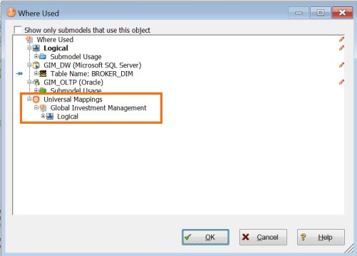
Universal Mappings are displayed in the object's Where Used tab.
You can also see the mappings of an object by right-clicking the object and selecting Where Used.
And you can see the mappings of an object in the Universal Mappings Editor.
Viewing and Editing Denormalization Mappings
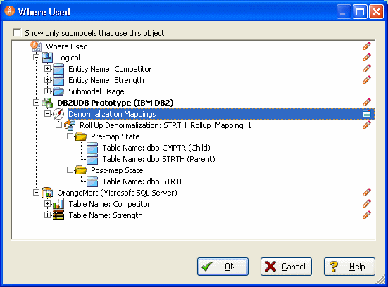
The history of a table's denormalization is stored with the table and can be viewed on the Where Used tab of the Table Editor. Where Used information can also be accessed using the Edit User-Defined Mappings function available on the right-click menu of a table. From the Where Used tab or window you can see how the table was transformed.
- From the Data Model Window, right-click the table you want to learn about and select Where Used.
- The Where Used tab or window presents a graphical tree/node representation of the denormalization. In the screenshot below, by expanding the Denormalization Mappings entry, you can see what type of denomalization transformed the table. You can also see the pre-map and post-map state of the table. The example below shows that two tables, CMPTR and STRTH were rolled up into STRTH. On the right of the screen is an icon that let you edit the mapping
 .
.
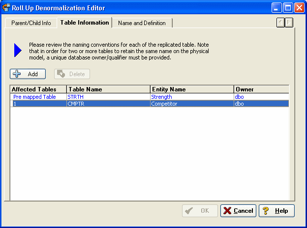
- To edit the Denormalization mapping, click the edit mapping icon.

![]() Note: If, after you perform a denormalization, you want to revert the table to its premap state and the undo operation is no longer available you must perform the reverse denormalization. For example, if you rolled up two tables you must select the table and then perform a roll-down denormalization on it, splitting up the one table into two.
Note: If, after you perform a denormalization, you want to revert the table to its premap state and the undo operation is no longer available you must perform the reverse denormalization. For example, if you rolled up two tables you must select the table and then perform a roll-down denormalization on it, splitting up the one table into two.
