UML 1.5 Sequence Diagram Definition
Go Up to UML 1.5 Interaction Diagrams
Class diagrams are static model views. In contrast, interaction diagrams are dynamic, describing how objects collaborate.
Definition
A sequence diagram is an interaction diagram that details how operations are carried out: what messages are sent and when. Sequence diagrams are organized according to time. The time progresses as you go down the page. The objects involved in the operation are listed from left to right according to when they take part in the message sequence.
Sample Diagram
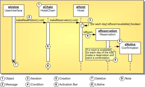
Following is a Sequence Diagram for making a hotel reservation. The object initiating the sequence of messages is a Reservation window (the UserInterface).
The UserInterface sends a makeReservation() message to a HotelChain. The HotelChain then sends a makeReservation() message to a Hotel. If the Hotel has available rooms, then it makes a Reservation and a Confirmation.
Each vertical dotted line is a lifeline, representing the time that an object exists. Each arrow is a message call. An arrow goes from the sender to the top of the activation bar of the message on the receiver's lifeline. The activation bar represents the duration of execution of the message.
In this diagram, the Hotel issues a self call to determine if a room is available. If so, then the Hotel creates a Reservation and a Confirmation. The asterisk on the self call means iteration (to make sure there is available room for each day of the stay in the hotel). The expression in square brackets, [ ], is a condition.
The diagram has a clarifying note, which is text inside a dog-eared rectangle. Notes can be included in any kind of UML diagram.
