UML 1.5 Component Diagram Definition
Go Up to UML 1.5 Component Diagrams
Both component and deployment diagrams depict the physical architecture of a computer-based system. Component diagrams show the dependencies and interactions between software components.
Definition
A component is a container of logical elements and represents things that participate in the execution of a system. Components also use the services of other components through one of its interfaces. Components are typically used to visualize logical packages of source code (work product components), binary code (deployment components), or executable files (execution components).
Sample Diagram
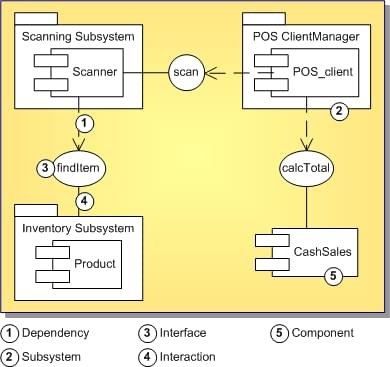
Following is a component diagram that shows the dependencies and interactions between software components for a cash register program.
