UML 1.5 Statechart Diagram Definition
Go Up to UML 1.5 Statechart Diagrams
This topic describes the UML 1.5 Statechart Diagram.
Definition
Objects have behaviors and states. The state of an object depends on its current activity or condition. A statechart diagram shows the possible states of the object and the transitions that cause a change in state.
Sample Diagram
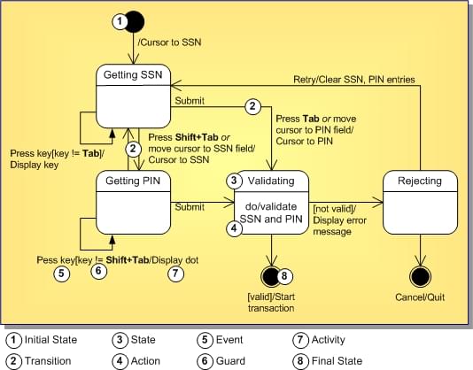
The following diagram models the login part of an online banking system. Logging in consists of entering a valid social security number and personal id number, then submitting the information for validation. Logging in can be factored into four non-overlapping states: Getting SSN, Getting PIN, Validating, and Rejecting. Each state provides a complete set of transitions that determines the subsequent state.
States are depicted as rounded rectangles. Transitions are arrows from one state to another. Events or conditions that trigger transitions are written next to the arrows. This diagram has two self-transitions: Getting SSN and Getting PIN. The initial state (shown as a black circle) is a dummy to start the action. Final states are also dummy states that terminate the action.
The action that occurs as a result of an event or condition is expressed in the form /action. While in its Validating state, the object does not wait for an outside event to trigger a transition. Instead, it performs an activity. The result of that activity determines its subsequent state.
